Organic photovoltaics (OPV) possess the advantages of lightweight, thinness, flexibility, semi-transparency, and solution-based printing preparation, exhibiting great potential in portable photovoltaic cells and wearable electronic devices. However, vacuum deposition remains the mainstream approach for preparing OPV top electrodes, which suffers from long periods, low output, and high costs, posing a significant bottleneck to roll-to-roll printing.
It is of great significance to promote the industrialization process of OPV to study new electrode materials and preparation processes, which can balance device efficiency and are suitable for industrial production. Printing the top electrode of OPV by solution method contributes to realizing the all-printing of OPV devices.
Field’s Metal (FM) is a low-melting-point alloy that exhibits high electrical conductivity and a low work function, rendering it an ideal material for use as an OPV cathode. FM’s liquid-to-solid phase transformation can be attained by adjusting the temperature, which eliminates the need for vacuum or solvent evaporation during the fabrication of FM top electrodes for OPV devices. However, the printing of thin-film electrodes with controllable thickness and width from FM has proven challenging due to the high surface tension of low-temperature alloys.
To address this issue, Professor Weiwei Deng’s research team from the Department of Mechanics and Aerospace Engineering at the Southern University of Science and Technology (SUSTech) has developed a flexible scraping method to fabricate FM thin films quickly and conveniently as top electrodes for OPV devices. By leveraging this method, they successfully fabricated a high-performance fully-printed OPV device.
Their research work, entitled “Blade coating of alloy as top electrodes for efficient all-printed organic photovoltaics,” has been published in Advanced Functional Materials, a well-regarded academic journal.
The electrode printing apparatus is shown in Figure 1a. The flexible blade used is a thin sheet of Teflon. Using a flexible blade (Figure 2a) can ensure close contact between the scraper and the mask during the scraping process, avoiding leakage of the molten alloy. Tungsten film mask is used to limit the width and thickness of the film. During the printing process, the substrate temperature is maintained at 68 °C to keep the FM in a liquid state. The movement speed and distributed load of the blade are controlled by a three-dimensional moving platform for blade-coating.
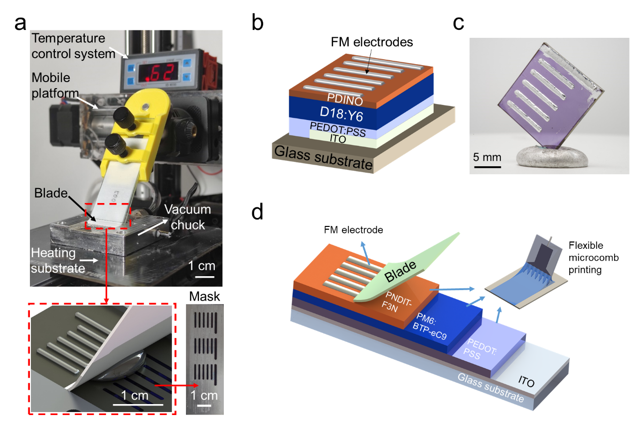
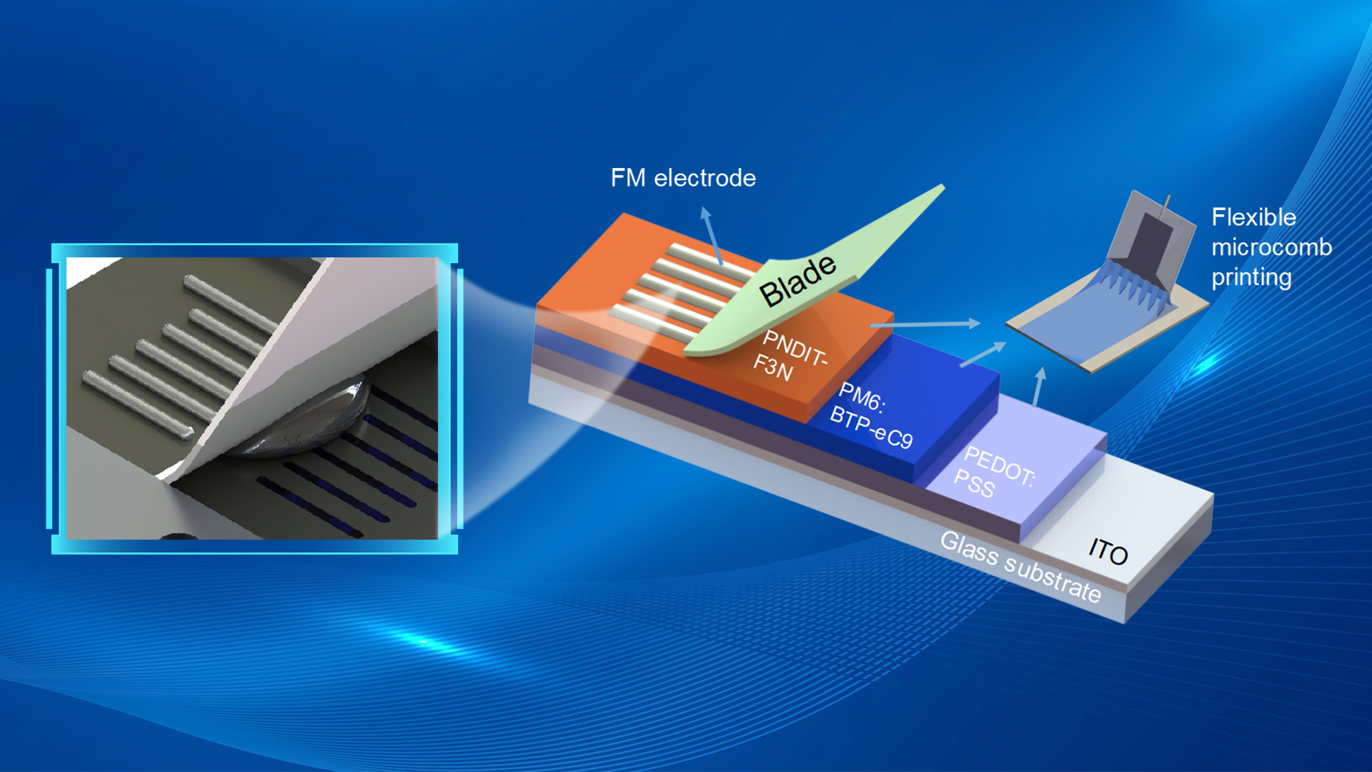
Figure 1. (a) Photograph of the electrode printing apparatus and the schematic details of the flexible blade coating of FM electrodes. (b) Configuration of the OPV device with FM as top electrodes. (c) Photograph of the finished devices. (d) All-printed device architecture and the schematic of the fabrication process.
The fluid mechanics and material mechanics issues during the process of flexible blade-coating were studied. The cross-section views along and perpendicular to the printing direction are shown in Figures 2b and 2c, respectively. In the parallel direction, the blade and the opening of the mask form a connector. The liquid metal in front of the blade may reflow into the film by gravity due to the height difference between the printed film and the FM stored in front of the blade, forming a film thicker than the mask thickness. In the vertical direction, as the PTFE blade descends from the initial state, the pressing force increases approximately linearly with the vertical displacement of the blade holder (Figure 2e), and the degree of bending increases (Figure 2d).
In order to avoid damage to the organic layers by the bending of the blade touching the substrate, the maximum deflection should be less than the mask thickness. Figures 2g-i respectively show the effects of distributed load, the opening width of the mask, and printing speed on the thickness of low-temperature alloy films. The opening width of the mask, distributed load, and printing speed can be adjusted according to the actual needs to obtain electrodes with appropriate thickness.
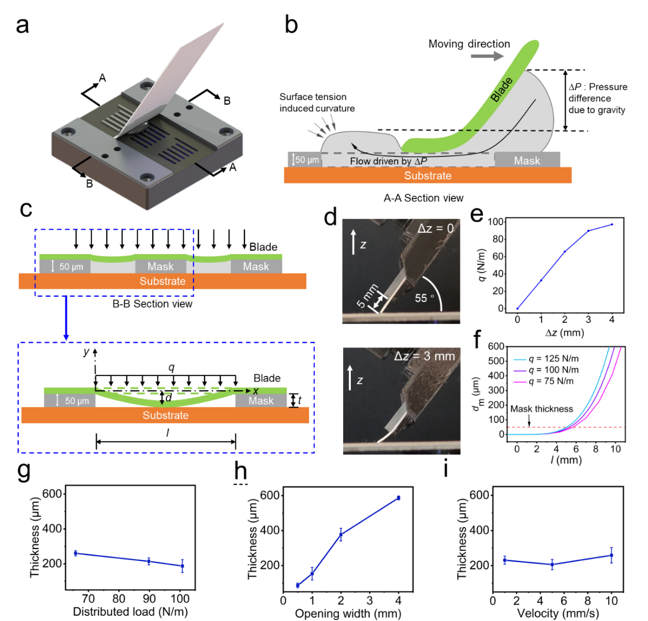
Figure 2. (a) 3D rendering of blade coating of the FM electrodes on the Tungsten mask. (b) Cross-section view along the printing direction. (c) Cross-section view perpendicular to the printing direction, and the inset shows the beam model with distributed load. (d) Side views of the PTFE blade contacting the substrate: top image is the initial state of the PTFE blade just in touch with the substrate (Dz = 0); bottom image is the blade under the pressing force at Dz = 3 mm. (e) The distributed loads at the pressing distances of Dz = 1, 2, 3, and 4 mm. (f) The maximum deflection of the blade (dmax) vs. the opening width (l) of the mask. The thicknesses of the printed FM traces: (g) under different distributed loads (q = 66, 90, and 97 N/m) with l = 1 mm, (h) using masks with different opening widths (l = 0.5, 1, 2, and 4 mm) under q = 90 N/m, and (i) at different printing speed (V = 0.5, 5, and 10 mm/s) with l = 1mm and q = 90 N/m.
Based on the D18:Y6 system, FM top electrode is blade-coated on the spin-coated organic functional layers, achieving a PCE of 17.28% (Figure 3a). For all-printed OPVs based on the PM6:Y6 system, FM top electrode was also used. At the same time, other organic layers were prepared by flexible microcomb printing, achieving a PCE of 16.07%, which is the highest value reported to date for all-printed OPVs, as summarized in Figure 3b. Furthermore, the devices with blade-coated alloy electrodes show better thermal and air stability than those with evaporated-Ag electrodes (Figure 3c and d).
Figure 3e shows the optical microscopic images of Ag and FM electrodes before and after 120-hour lifetime tests in an N2 glovebox, under AM 1.5G photo illumination and under 55°C heating. After photo- and thermal-stability tests, the edges of the Ag electrodes become blurry and darkened, indicating deterioration of Ag, which causes the drop in OPV performance. However, the edges of FM electrodes remain sharp and bright for all conditions. The results confirm that the FM electrode is more stable than the Ag electrode, especially under illumination or higher temperature.

Figure 3. (a) highest reported PCEs of OPVs with the evaporation-free top electrode, (b) PCE evolution of all-printed OPVs on ITO electrodes. (c) decays of normalized PCEs of unencapsulated devices in N2 glovebox under room temperature and 55 °C. (d) decays of normalized PCEs of unencapsulated devices in the air under room temperature and 55 °C. (e) optical microscopic images of Ag and FM electrodes before and after 120-hour lifetime tests in an N2 glovebox, under AM 1.5G illumination, and under 55°C heating.
Master’s student Linna Liu and Ph.D. student Boyang Yu, both of the Department of Mechanics and Aerospace Engineering at SUSTech, are the co-first authors of this paper. Master’s student Liangyuqi Kang is the co-author while Research Assoc. Prof. Xinyan Zhao of the Academy for Advanced Interdisciplinary Studies at SUSTech and Prof. Weiwei Deng are the co-corresponding authors.
This work was supported by the National Natural Science Foundation of China (NSFC), Shenzhen Key Laboratory of Soft Mechanics & Smart Manufacturing, and the Joint Laboratory of SUSTech MAE and Jin Xin Technology.
Paper link: https://doi.org/10.1002/adfm.202214781
To read all stories about SUSTech science, subscribe to the monthly SUSTech Newsletter.
Proofread ByAdrian Cremin, Yingying XIA
Photo By


