With the rapid growth of the digital economy, developing rechargeable batteries with stable and high energy has been pushed to an extremely urgent level. LiCoO2 (LCO) is one of the utmost successful cathode materials for lithium-ion batteries (LIBs) because of its several inherent advantages, including ultra-high tapping density, high-voltage plateau, and ease of mass production.
The energy level of Co3+ (3d6), which is located very closely with O2- (2p6), makes LCO undergo complex phase transitions at high voltage. Therefore, the charge cut-off voltage has to be restricted to 4.2V to avoid structure collapse, corresponding to a reversible capacity of only 140 mAh g-1. It remains a big challenge to further increase the voltage over 4.6V, approximating a capacity of 220 mAh g-1.

Professor Zhouguang Lu’s group from the Department of Materials Science and Engineering (MSE) at the Southern University of Science and Technology (SUSTech) has recently achieved stable cycling of LCO at 4.6V through hierarchical doping engineering with inert P-outside and active Ni-inside dual doping. This ingenious outside-in structure design enables Ni2+ to occupy at Li layer in the bulk layered phase and P gradient doping at the superficial lattice.
Their research, entitled “Hierarchical Doping Engineering with Active/Inert Dual Elements Stabilizes LiCoO2 to 4.6V,” was published online in Advanced Energy Materials, a high-profile journal in material science.
The doped active Ni2+ can not only serve as a “pillar” to restrain the formation of metastable H1-3 phase, but also regulate the electronic structure of LCO and trigger the superexchange interaction of Ni2+-O-Co4+, altogether with the strong P-O coordination to substantially suppress the lattice oxygen escape from the surface (Figure 1). Therefore, it considerably reduces the risk of layer structure collapse and lattice oxygen escaping, achieving stable and high-capacity operation over 4.6V. This hierarchical outside-in doping strategy is inspiring in stabilizing high-energy electrode materials working under high voltages.
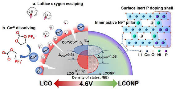
Figure 1. Schematic illustrations of the hierarchical outside-in doping strategy with Ni and P to stabilize LiCoO2 to 4.6V.
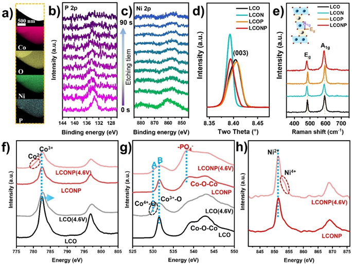
Figure 2. Structural characterization of the hierarchical doped LiCoO2 with active Ni/inert P dual elements.
From the local region elemental mappings and the XPS depth profiles (Figure 2a-c), it can be seen that both Ni and P elements distributed uniformly over LCONP particle, wherein P element was enriched at the outmost shell and Ni element distributed uniformly within the bulk region. Moreover, from the high-resolution X-ray diffraction (HRXRD) and Raman spectra, as shown in Figures 2d and e, it can be found that the interplanar spacing of LCONP was slightly enlarged due to the effective introduction of Ni2+ inside the bulk layered structure, as its XRD (003) peak and Raman A1g/Eg peaks shifted towards lower wave numbers.
Displayed in the soft X-ray absorption spectra, as shown in Figures 2f and g, the LCONP accumulated less Co4+ than LCO and produced some Co2+ at 4.6V, implying its possible electronic state modulation happened within the inner structure. In addition, Ni in LCONP also exhibited two chemical environments (Figure 2h), indicating its two possible occupying sites within LCONP. Furthermore, the -PO4 structure shown in Figure 2g proved that the P element was effectively doped into the LCONP lattice, which contributes to stabilizing the lattice oxygen through the strong P-O bond.
In the EPR spectrum in Figure 3, the initial LCONP appears as a Ni3+ signal with a symmetric Lorentzian line shape, indicating that some Ni3+ has been doped in the transition metal layer. This can form a 180° superexchange interaction with the Ni2+ at the Li site. Upon charging to 4.6V, the Ni3+ signal gradually disappeared because it was oxidized to Ni4+; meanwhile, the Co3+ partially transformed to Co4+. Compared with the closed-shell Ni4+, the Co4+ appearing at high voltage presents an open-shell electronic configuration. Therefore, it can be speculated that the Ni2+ at Li sites would trigger a new superexchange interaction with Co4+. This plays an important role in regulating the electronic state configuration of Co and O at high voltage, as observed from the SXAS results.
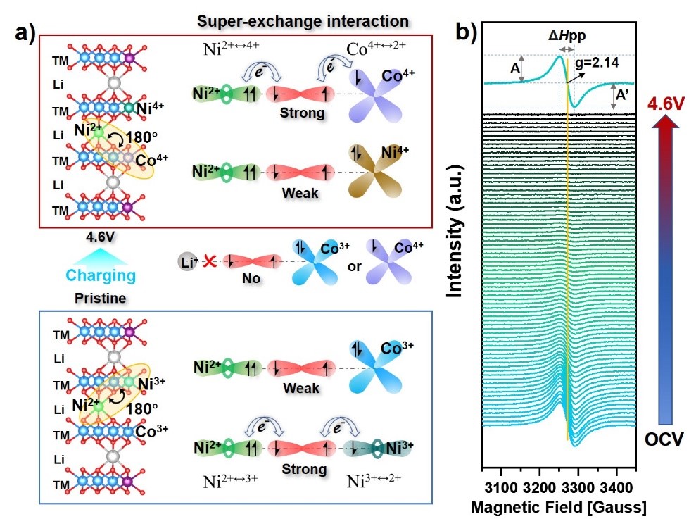
Figure 3. Schematic of the superexchange interaction between NiLi site and TMTM site within LCONP at pristine and 4.6V states and corresponding in situ EPR spectra.
To evaluate the effectiveness of LCONP on the cycling and rate performance under 4.6V, electrochemical tests were conducted in half-cells, as shown in Figure 4. LCONP delivers a high reversible discharge capacity of nearly 220 mAh g-1 at 0.1C and outstanding capacity retention of 92.6% after 100 cycles. The LCONP also displays better rate performance at 5C than LCO, holding impressive capacity retention of 166 mAh g-1.
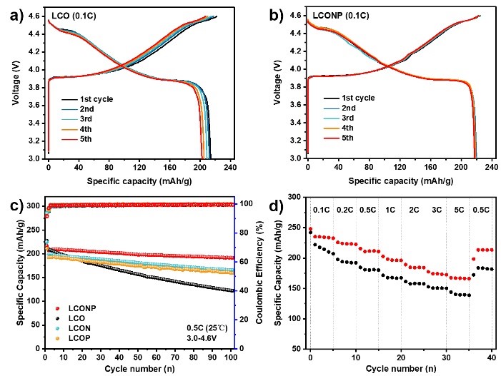
Figure 4. The battery performance comparison of LCONP and LCO.
To make clear the implicit mechanism of LCONP licensed superior stability at high voltage, in situ XRD measurements were conducted by the researchers to monitor the structural transformation upon charging/discharging. From the (003) peak evolution and corresponding contour plot pattern (Figure 5a and b) upon the first cycle, it can be seen that less evident O3 to H1-3 phase transition and restrained violent volume change occurred on LCONP than LCO, which can be attributed to the “pillar effect” of Ni2+ at Li sites. It was also verified from dQ dV-1 curves, as shown in Figure 5c, wherein the oxidation peak centered at ≈ 4.55V belonging to O3 to H1–3 phase transformation for LCONP was weaker than LCO.
From the electrochemical impedance spectroscopy (EIS), it can also be observed that LCONP delivers more fluent Li ion diffusion performance than LCO at different charge states. After re-discharging to 3.0V, its charge-transfer resistance (Rct) and Li-ion diffusion coefficient (DLi+) can be recovered better than LCO, suggesting that a more stable electrode/electrolyte interface can be formed on LCONP even after undergoing high delithiation state.
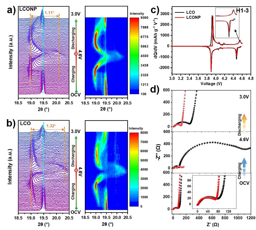
Figure 5. The (003) peaks evolution of in situ XRD pattern and corresponding contour plot for a) LCONP and b) LCO cathodes during the first charge-discharge process at 0.2 C in the voltage window of OCV–4.6V-3.0V. c) dQ dV-1 curves of LCO and LCONP at 0.1 C. d) EIS spectra of LCO and LCONP collected at OCV, 4.6V, and 3.0V after the initial cycle.
To further probe the evolution mechanism of lattice oxygen at high voltage, ex-situ XPS and in situ Raman were conducted by Prof. Lu’s team to monitor the O-related signal evolution tendency. They observed that the peak of lattice O for LCO negatively shifted to 528.9 eV at 4.6V (Figure 6a), implying its markedly weakened binding energy at a deep delithiation state. In contrast, almost no change occurred on the signal for LCONP from OCV to 4.6V, owing to duplicate protection of pillared Ni and strong P-O bond as mentioned above.
From the in situ Raman results, as shown in Figures 6b and c, the peak intensity of A1g (Co–O stretching vibration) and Eg (O–Co–O bending vibration) for LCO attenuated evidently, indicating that the bonding between Co and O became feeble after going through deep delithiation under 4.6V. Furthermore, an irreversible peak of (O2)2- intermediates can be found for LCO at around 850 cm-1 within the high voltage range, signifying that the lattice oxygen has been irreversibly oxidized and escaped from the lattice. In comparison, more reversible A1g and Eg evolution and no signal of (O2)2- intermediates appeared for LCONP during the cycle process, indicating that its chemical bond of lattice oxygen within LCONP can be maintained stable at high voltage.
In the TOF-SIMS spectra (Figure 6d and e), it can also be revealed that there is less accumulation of O species within the cathode electrolyte interphase (CEI) for LCONP than LCO after 50 cycles. The DFT calculation results show that Ni2+ doped at Li sites helps to increase the separation of Co 3d and O 2p energy bands, especially at high voltage. This suggests that Ni2+ can effectively modulate the energy band structure of LCONP and reduce the charge compensation and instability of lattice O at high voltage.

Figure 6. (a) Ex situ XPS O 1s spectra for LCO and LCONP at pristine and 4.6V voltage. Contour map of in situ Raman pattern collected from the monochromatic laser with an excitation line of 532 nm for b) LCONP and c) LCO cathodes during the first charging/discharging process at 0.1 C between 3.0-4.6V. Top view of TOF-SIMS data for O distributed in CEI of d) LCONP and e) LCO after 50 cycles. (f) The diagrams of the energy gap between Co3d and O2p band center for LCO and LCONP at different states calculated by DFT.
Ning Qin, a visiting student at SUSTech, is the first author of this paper. Prof. Zhouguang Lu from SUSTech and Prof. Kaili Zhang from the City University of Hong Kong (CityU) are the co-corresponding authors. Qingmeng Gan, Zhaofeng Zhuang, Yanfang Wang, Yingzhi Li, and Zhiqiang Li from Prof. Lu’s research group also contributed to this study.
This work was financially supported by the Basic Research Project of the Shenzhen Science and Technology Innovation Commission, Shenzhen Key Laboratory of Interfacial Science and Engineering of Materials, National Natural Science Foundation of China (NSFC), and the Research Matching Grant Scheme (RMGS).
The authors also acknowledge the support of both the Core Research Facilities and the Center for Computational Science and Engineering at SUSTech. The XAFS experiments were conducted in the BL08U1A Beamlines at the Shanghai Synchrotron Radiation Facility (SSRF).
Paper link: https://onlinelibrary.wiley.com/doi/10.1002/aenm.202201549
To read all stories about SUSTech science, subscribe to the monthly SUSTech Newsletter.
Proofread ByAdrian Cremin, Yingying XIA
Photo By